

There are many parameters to consider when choosing turning insert. Carefully select insert geometry, insert grade, insert shape (nose angle), insert size, nose radius and entering (lead) angle, to achieve good chip control and machining performance.
- Select insert geometry based on selected operation, for example finishing
- Select the largest possible nose angle on the insert for strength and economy
- Select the insert size depending on the depth of cut
- Select the largest possible nose radius for insert strength
- Select a smaller nose radius if there is a tendency for vibration
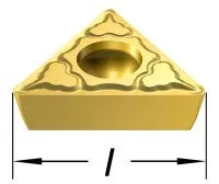
l = cutting edge length (insert size)
Turning insert geometry
Turning geometries can be divided into three basic styles that are optimized for finishing, medium and roughing operations. The diagram shows the working area for each geometry, based on acceptable chip breaking, in relation to feed and depth of cut.
Roughing
High depth of cut and feed rate combinations. Operations requiring the highest edge security.
Medium
Medium operations to light roughing. Wide range of depth of cut and feed rate combinations.
Finishing
Operations at light depths of cut and low feed rates. Operations requiring low cutting forces.
Turning Wiper geometry
Use wiper inserts for improved surface finish with standard cutting data, or, maintained surface finish at substantially higher feed rate.
The -WMX wiper geometry is first choice, and is a good starting point for most applications. When conditions change, there is always a productive alternative.
Choose a positive wiper geometry to lower forces and maintain productivity in case of vibration problems.
Choose wiper geometry as follows:
-WL: For improved chip control when moving to a lower fn/ap.
-WF: Improves chip control at a lower fn/ap. Also for lower cutting forces when vibrations occur.
-WMX: Always first choice within the wide chip application area. Provides maximum productivity, versatility and the best results.
-WR: When a stronger edge line is needed, for example, for interrupted cuts.
Turning insert grade

The insert grade is primarily selected according to:
- Component material (ISO P, M, K, N, S, H)
- Type of method (finishing, medium, roughing)
- Machining conditions (good, average, difficult)
The insert geometry and insert grade complement each other. For example, the toughness of a grade can compensate for lack of strength in an insert geometry.
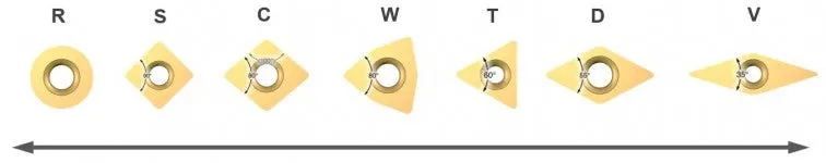
Turning insert shape
The insert shape should be selected relative to the entering angle accessibility required of the tool. The largest possible nose angle should be selected to provide insert strength and reliability. However, this has to be balanced against the variation of cuts that need to be performed.
A large nose angle is strong, but requires more machine power and has a higher tendency for vibration.
A small nose angle is weaker and has a small cutting edge engagement, both of which can make it more sensitive to the effects of heat.
Cutting edge strength (Large nose angle)
- Stronger cutting edge
- Higher feed rates
- Increased cutting force
- Increased vibration
Less vibration tendencies (Small nose angle)
- Increased accessibility
- Decreased vibration
- Decreased cutting force
- Weaker cutting edge
Turning insert size
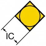
Select insert size depending on the application demands and the space for the cutting tool in the application.
With a larger insert size, the stability is better. For heavy machining, the insert size is normally above IC 25 mm (1 inch).
When finishing, the size can in many cases be reduced.
How to choose insert size
- Determine the largest depth of cut, ap
- Determine the necessary cutting length, LE, while also considering the entering (lead) angle of the tool holder, the depth of cut, ap, and the machine specification
- Based on the necessary LE and ap, the correct cutting edge length, L, and IC for the insert can be selected
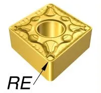
Turning insert nose radius
The nose radius, RE, is a key factor in turning operations. Inserts are available in several sizes of nose radius. The selection depends on depth of cut and feed, and influences the surface finish, chip breaking and insert strength.
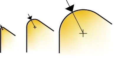
| Small nose radius | Large nose radius | |
|
|
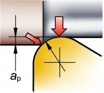
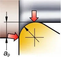
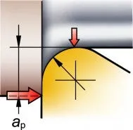
Depth of cut and cutting forces
The relationship between nose radius and depth of cut affects vibration tendencies. The radial forces that push the insert away from the cutting surface become more axial as the depth of cut increases.
It is preferable to have more axial forces than radial. High radial forces can have a negative effect on the cutting action which can lead to vibration and bad surface finish.
As a general rule of thumb, choose a nose radius that is equal or smaller than the depth of cut.
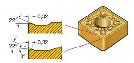
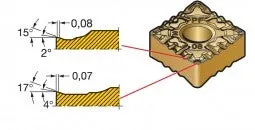
Positive or negative turning insert style
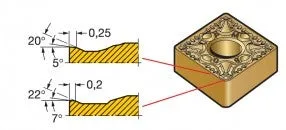
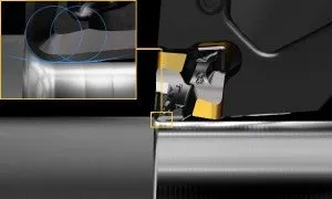
A negative insert has an angle of 90° (0° clearance angle), while a positive insert has an angle of less than 90° (for example, 7° clearance angle). The illustration of the negative style insert, shows how the insert is assembled and tilted in the holder. Some characteristics of the two insert types are listed below:
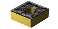
Positive turning insert
- Single sided
- Low cutting forces
- Side clearance
- First choice for internal turning and for external turning of slender components

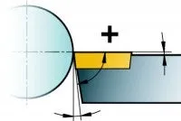
Clearance angle
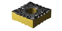
Negative turning insert
- Double and/or single sided
- High edge strength
- Zero clearance
- First choice for external turning
- Heavy cutting conditions

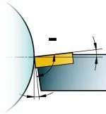
Clearance angle
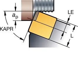
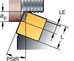
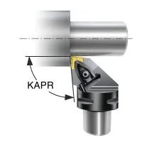
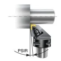
Entering angle for turning
The entering angle, KAPR (or lead angle, PISR), is the angle between the cutting edge and the feed direction. It is important to choose the correct entering/lead angle for a successful turning operation. The entering/lead angle influences:
- Chip formation
- Direction of cutting forces
- Cutting edge length in cut
Large entering angle (small lead angle)
- Forces are directed toward the chuck. There is less tendency for vibration
- Ability to turn shoulders
- Higher cutting forces, especially at the entrance and exit of the cut
- Tendency for notch wear in HRSA and case-hardened workpieces
Small entering angle (large lead angle)
- Increased radial forces directed into the workpiece will cause a tendency for vibration
- Reduced load on the cutting edge
- Produces a thinner chip = higher feed rate
- Reduces notch wear
- Can not turn a 90° shoulder


